Note: more pictures can be found in this album.
4k 120Hz, 1080p240Hz, 720p 300Hz, 540p 480Hz PWM-free + scanning backlight
OK, I should have your attention now. This is a story of how such a monitor came to be.
Four years ago, the first 4k displays had just started to become available. Often hobbled by the slow inputs of the time, 30Hz was common and one manufacturer, Innolux, offered some of their displays as 1080p120 input as well as 4k30. Skipping ahead to the end of 2015, I found myself in a unique situation. Living in China for two years with no obligations, negligible expenses, I began to offer the first 1080p240Hz displays on the market in early 2016. With 4k becoming popular and a year of time left, I set out to also be the first to offer 4k120Hz.
For a bit of background information, a typical display looks something like the system shown in figure 1.
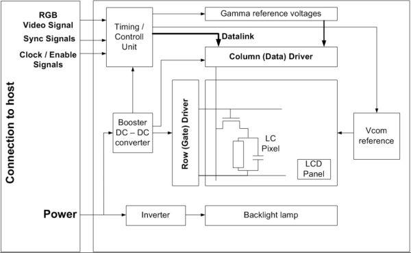
The “Timing/Control unit” in Figure1 is called the TCON. It handles driving the row and column drivers which in turn drive the pixel matrix. With all of the data flowing through the TCON, it is often the bottleneck when it comes to trying to drive the panel at a higher refresh rate.
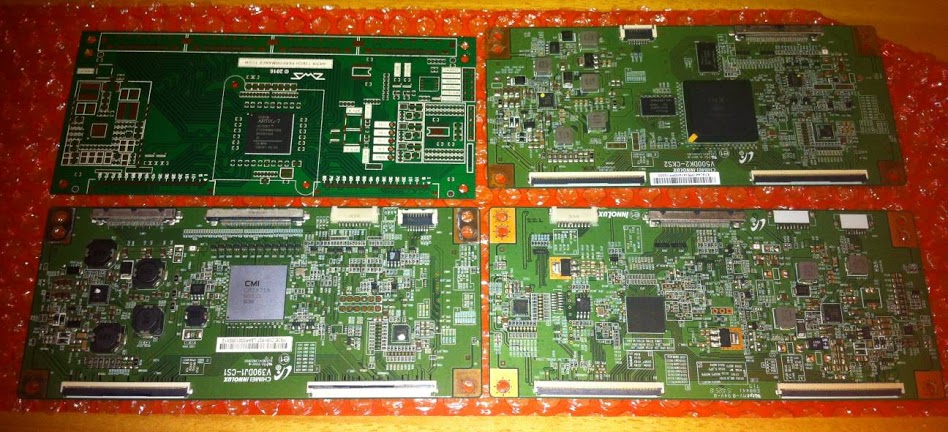
Surveying what was available on the market, I selected the Innolux line of 4k displays because the whole line, 28” TN, 39”/40”/42”/50”/58”MVA all used removable TCONs which appeared to be compatible with each other. Designing one TCON could potentially fill many market segments. Additionally, many people, including me, already owned good panels with slow electronics. I had a plan.
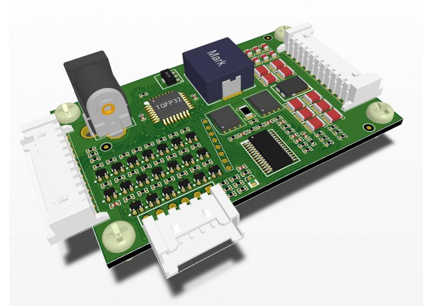
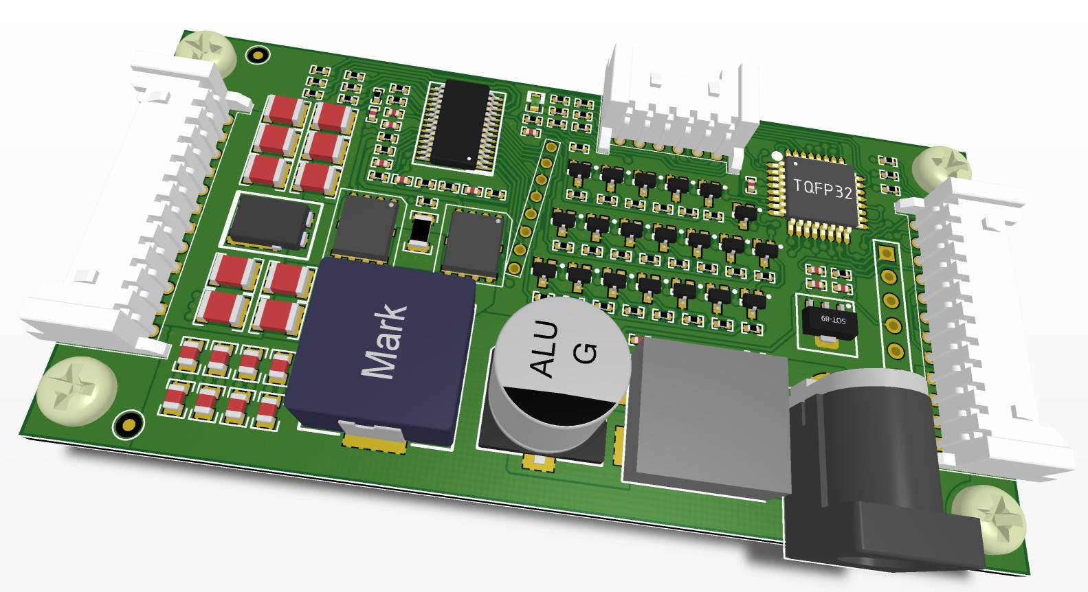
With no manufacturer support, I reverse engineered the pinouts and protocols of the TCON <=> PANEL interface. Some other design decisions were made at this point. The Artix7 FPGA was chosen for a balance of I/O capability and cost. LVDS interface was chosen to avoid high-cost SERDES requirements. From the 1080p240Hz display development, I already had DP1.2 to LVDS converter boards, so I had a front-end to test with as well. Six layers of PCB later, the tcon board was ready for assembly.
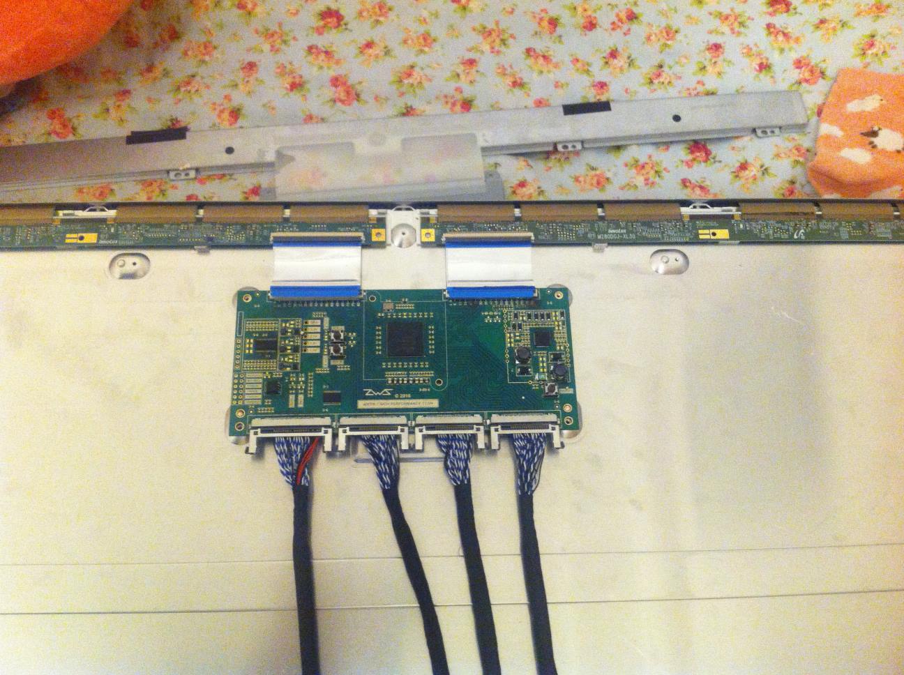
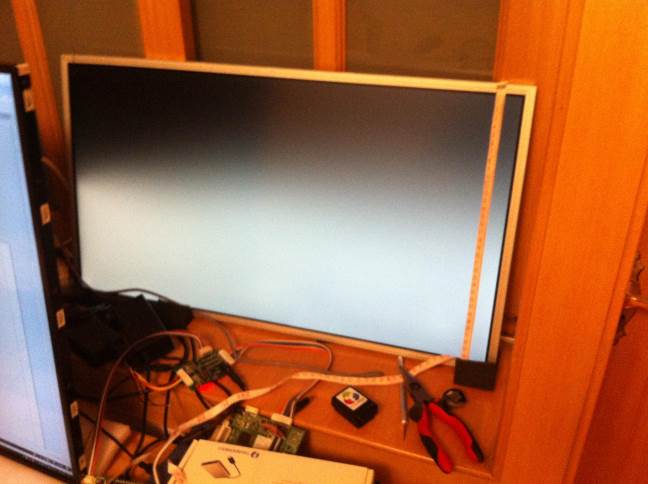
Soon, it was readyto be hooked up to the panel :
While the hardware design was good and working, it was time to program the FPGA. To do this, I had to learn how to program an FPGA. It had been 10+ years since touching the subject. Time to dig in!
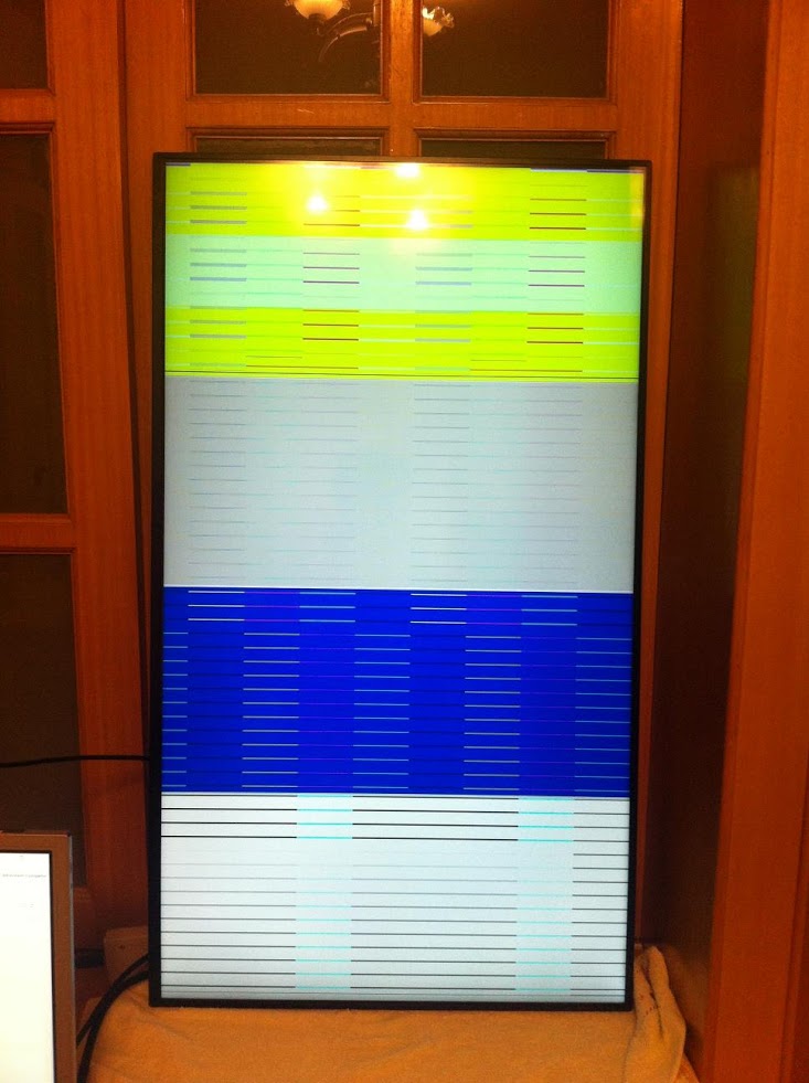
In the first step, the goal was to put a simple test pattern on the screen. Armed with scope captures, an understanding of the system, and much patience, I set to coding. Many compiles later, the first image on the screen appeared. This was a huge milestone, it meant that the project could work.
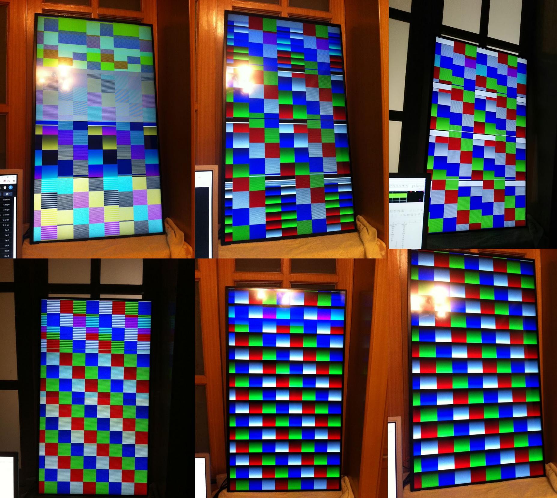
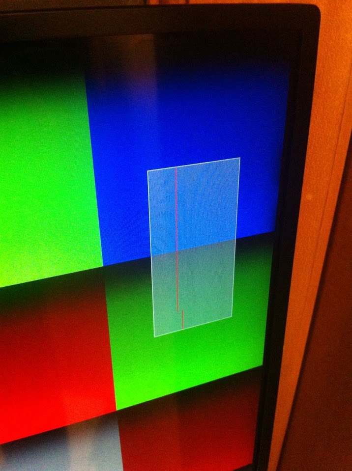
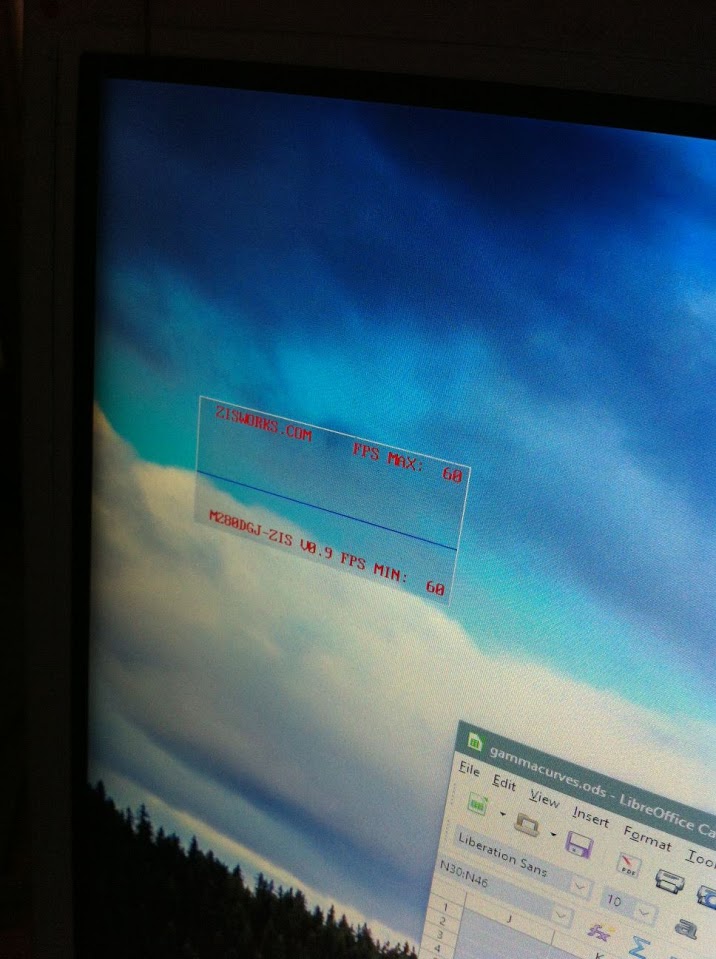
With the output block functional and correctly driving the panel at the full 4k120Hz speed, the project was looking promising. An on-screen-display was coded and aplhablended onto the video stream (no added latency). The OSD was intended to show a graph of the incoming framerate, for use with adaptive sync sources.
With the OSD done and the system working well with internal test patterns, the dual quad channel LVDS inputs were coded up based on a reference design from Xilinx, the fpga vendor. Later, the design was modified to dynamically adjust PLL and delay block configurations based on the input frequency to accommodate for a wide range of inputs.
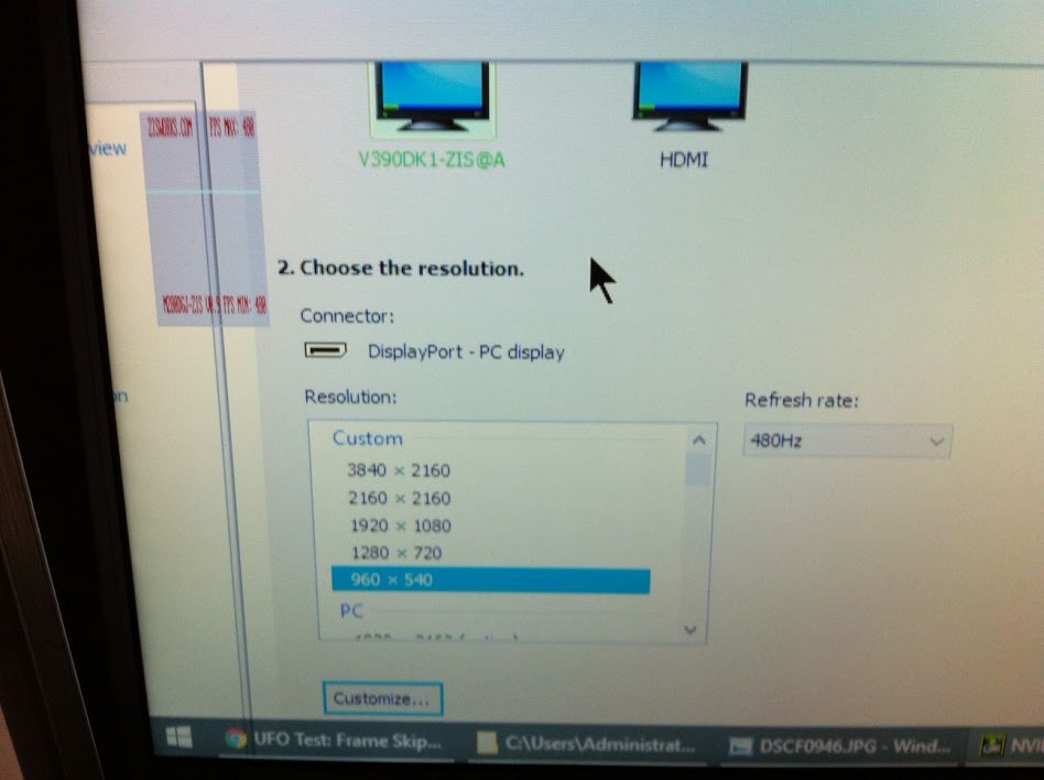
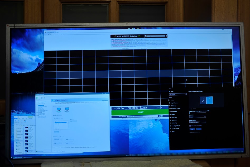
An integer scaling unit was added and testing with 1080p inputs began. By using the same data for multiple lines of pixels, the system could be operated at higher refresh rates. With some careful timing, rates of up to 480Hz were possible!
At this point, it was January 2017 and the display transitioned from the testbench and onto my desk. Still iterating and improving, the system was stable enough to be used as the primary display of the system developing it. A great milestone to be at.
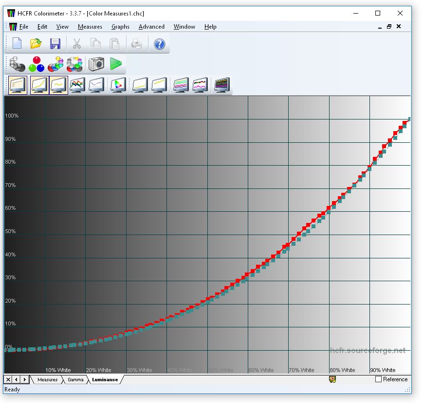
Though the display was working, color accuracy was terrible because the pixels were being driven with incorrect voltage levels. At the end of this massive stream of bits from a grahpics card lies a thin layer of liquid crystal material with a voltage accross it. The entire point of all of the electronics is to get that voltage to be correct for each of the 25 million subpixels. How this is accomplished is through precise digital to analog converters, one for each column of the display, but these are not your regular DACs. These DACs are packed tight, with nearly a thousand per chip, so they have to be simple. Another complication is that there are nonlinearities present in the system, so the mapping of digital values to voltages is nonlinear. Gamma voltages are the solution to this problem. A high precision DAC generates a handful of reference voltages and the column driver DACs linearly interpolate between the reference levels. Through adjusting the gamma reference voltage levels, the necessary transfer function mapping from digital values to output voltages can be accopmlished. This process is called gamma voltage tuning. Using a colorhug2 display calibrator as a light meter, the gamma voltage configuration was iteratively adjusted to minimize deviation from the desired optical response. A voltage profile was generated for each panel at each of the four supported refresh rates. Now the display looked good.
With the TCON becoming close to final, the input solution that was used for testing needed to be improved. It was determined that the DP2LVDS boards were incompatible with adaptive sync. Some other alternatives were tried, but ultimately, they were unsuccessful for one reason or another. DP2LVDS was chosen for the final version. A few months later and the system was essentially the same.
Now that the final decision to use DP2LVDS was made, something had to be done to make the two inputs easier to use. I carefully examined the EDIDs from Dell’s 5K display and determined the format of DisplayID and the tiled display extension block. Using new EDIDs, the display now appeared as a single logical display.
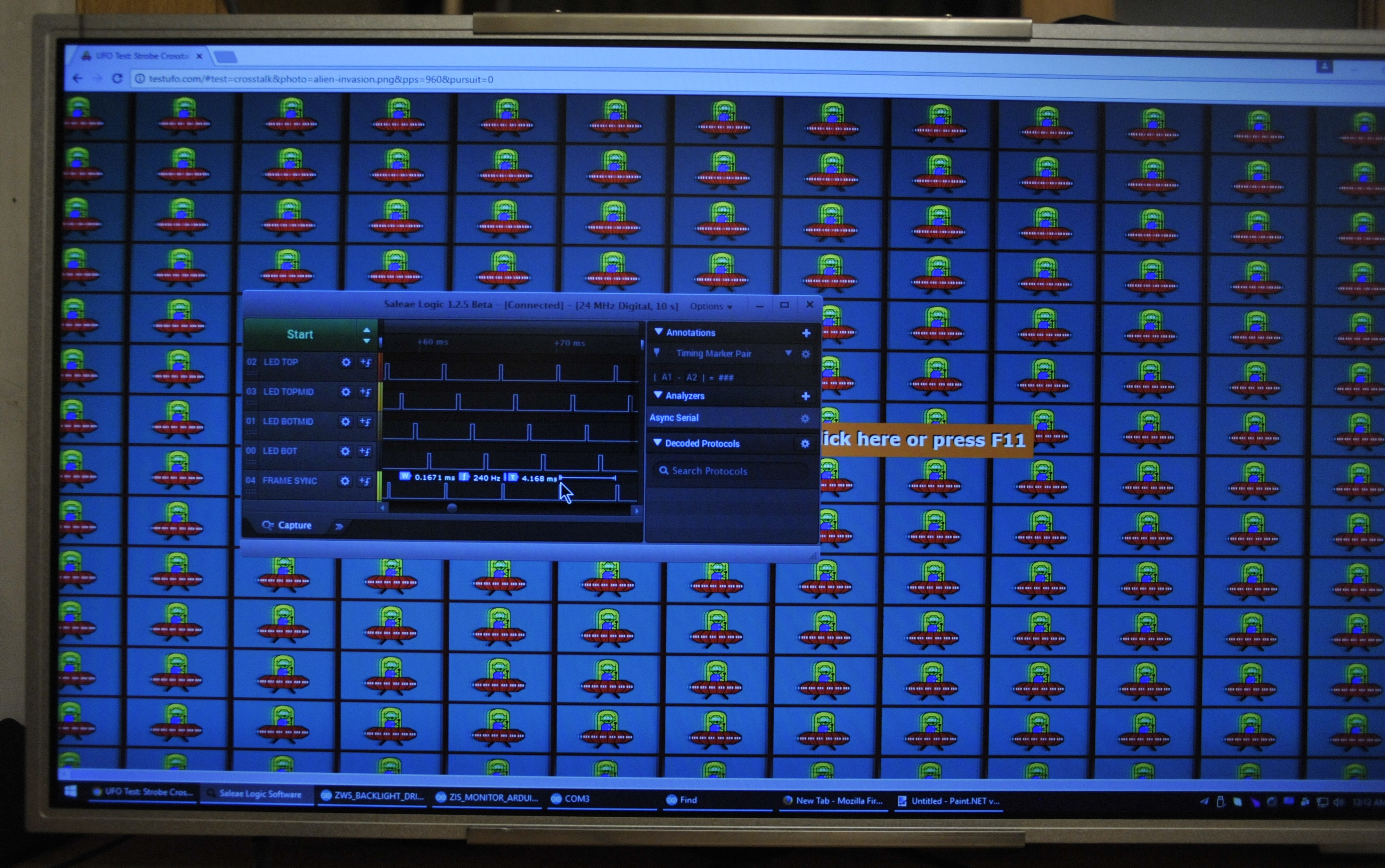
With variable refresh rates not an option, backlight strobing was the next big feature to add. A new backlight driver was developed to allow short pulses with high currents.
During the testing of this backlight driver, a fortuitous accident occurred : I fried a portion of the backlight. Why was this a good thing? I discovered that the backlight strip was arranged in segments along the left edge of the display. These LED strips are usually along the top or bottom edge of the display. Such an arrangement can be used for scanning!
A new backlight driver was made to support independent control over the different zones, and in scanning mode, carefully sequences pulses to maximize pixel transition times before each region is illuminated. The resulting effect is a blur-reducing backlight which offers clarity close to what a strobing backlgiht can do, but without the pentalty of requiring a long blanking period between frames. Global strobing mode is still available for those who want to use it.
And that, my friends, is how a single person developed a 4k120Hz + 1080p240Hz +540p480Hz display with a low-persistence backlight which can be used at full speeds. To sweeten the deal, the DP2LVDS and backlight driver will have open source firmwares easily modified with the Arduino IDE/environment.
Preorders are open and expected to ship in October 2017.
Thank you for reading and please check out the product page for info and the shop for detailed schedule and pricing info.